Block Diagram Of A Superheterodyne Am Rx

Explain The Working Of A Superheterodyne Receiver With The Help Of
Block Diagram Of A Superheterodyne Fm Rx Wiring Diagram
Understanding Selectivity

Diagram Block For Super Heterodyne Receiver End With Envelope

Block Diagram Of A Superheterodyne Am Rx Gain 5balmoond

Block Diagram Of A Superheterodyne Receiver Download Scientific

Related videos 1 https youtu be kwka1odpmum modulation techniques block diagram types of modulation 2 https youtu be d55 no4uzw0 amplitude modu.
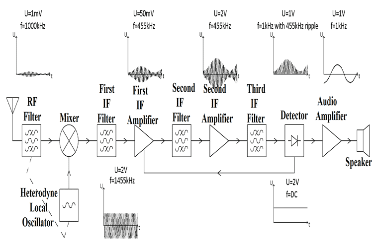
Block diagram of a superheterodyne am rx. Green are parts that operate at the intermediate frequency if while blue parts operate at the modulation audio frequency. These frequencies are applied to the mixer stage. It is useful to have an understanding of the different signal blocks their functions and the overall signal flow not only for the rf circuit design but also from an operational viewpoint. The limiter removes the noise in the received signal and gives a constant amplitude signal.
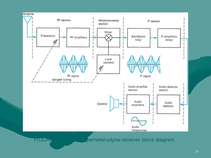
The block diagram of a typical transistor am superheterodyne receiver as you can see the block diagram has 11 different stages each stage has a specific function which is explained below. The working of a superheterodyne receiver is explained with the help of the block diagram given below in fig along with the waveforms at the output of each block. Totally different methods of demodulation. The output of the if amplifier is applied to the limiter circuit.
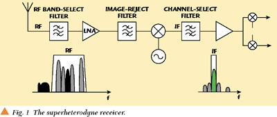
The rf carrier comes in from the antenna and is applied to a filter. The figure shows a block diagram of a typical superheterodyne receiver. Red parts are those that handle the incoming radio frequency rf signal. Need for limiting and de emphasis in fm.
The basic differences are as follows. Superheterodyne receiver in the superheterodyne receiver the incoming signal through the antenna is filtered to reject the image frequency and then amplified by the rf amplifier. The output of the filter are only the frequencies of the desired frequency band. The dotted line indicates that the local oscillator and rf filter must be tuned in tandem.
The superhet radio receiver is used in many forms of radio broadcast reception two way radio communications and the like. To understand how it works let s take a look at the superheterodyne am receiver block diagram which is shown below. Superhetrodyne receiver communication system btech part 39 0 00 introduction 1 35 block diagram of superheterodyne receiver 5 55 advantage of supehetrodyne receiver 7 10 frequency parameter. Fm receiver block diagram.
Block diagram of a typical superheterodyne receiver. Superheterodyne fm receiver block diagram. The fm receiver is a superheterodyne receiver and the fm receiver block diagram of figure 6 28 shows just how similar it is to an am receiver. The block diagram for the superheterodyne receiver shows the operation of the different signal blocks and the overall signal flow.
Radio Receivers Home

27mhz Superhet Am Receiver Simple Circuit Circuit Diagram Radio

Block Diagram Of A Superheterodyne Fm Rx Kobe Balmoond19

Edn Build Your Own Superheterodyne Receiver
Small Wonder Qrp 2016
Chapter 3 Am Receivers

Amplitude Modulation 2 3 Am Receivers Ppt Download

Whitelan Converter Block Diagram The Rx Path Is Shown In The Blue

Wireless 101 Automatic Gain Control Agc Ee Times
On The Direct Conversion Receiver A Tutorial

Bcb Rx Without Coils

X And Ku Band Small Form Factor Radio Design Analog Devices

January 2018 Dian Kurniawan Yd1osc
