Block Diagram Of Xy Recorder

Xy Recorder Block Diagram Working Electronics And
Xy Recorder Working Principle Applications Of Xy Recorder
X Y Recorders Youtube

X Y Recorder Youtube
Http Www Idc Online Com Technical References Pdfs Electronic Engineering Xy Recorders Pdf

X Y Recorders Inductor Electrical Engineering

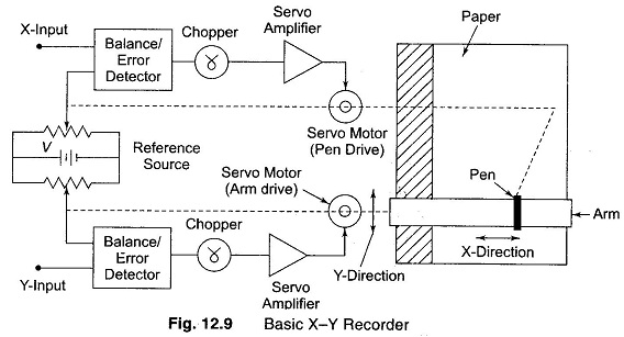
A signal enters each of the two channels.
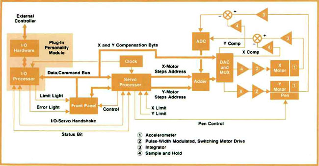
Block diagram of xy recorder. 5 block diagram of a typical x y recorder a signal enters each block of the two channels. Number of input channels can be provided for sampling and storage simultaneously. A coil is wound around the core. These recorders accept two inputs and create a chart or graph that displays the activity of one set of data against another.
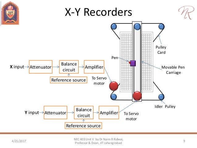
From the block diagram shown it can be seen that the input signal is applied to the amplifier in series with the part of the potentiometer. But when one of these two variables is time then there is a need for continuous recording and the chart advances with time. Multi pen multi ink plotting is possible. These recorders are used to measure the following.
12 9 each of the input signals is attenuated in the range of 0 5 mv so that it can work in the dynamic range of the recorder. Basic recorder block diagram. The balancing circuit then compares the attenuated signal to a fixed internal reference voltage. Analysis of records.
The x y recorder plots on a single stable chart. For example an xy recorder might be used in a chemical process to monitor the effect of temperature on. Tape recorder tutorial block diagrams electronics circuit and tutorials hobby science projects the tape head consists of a ring of soft magnetic material called the core with a small gap in it. T he constructional details are shown in figure.
Xy recorder block diagram working 1. Regulation curves of power supply. The signals are attenuated to the inherent full scale range of the recorder the signal then passes to a balance circuit where it is compared with an internal reference voltage. Such a recorder is named a strip chart recorder and it integrates some kind of accurate time base which advances the paper on a calibrated x axis.
A typical block diagram of an xy recorder working is illustrated in fig. They are useful for determining relationships between the two inputs. Plotting characteristics of active devices such as vacuum tubes. The self balancing type recorder is also called the potentiometric recorder.
The signals are attenuated to the inherent full scale range of the recorder the signal then passes to a balance circuit where it is compared with an internal reference voltage. Number of desired trigger modes can be incorporated. They have the provision to display pre trigger data.

Recording Storage And Display Devices Part 1

Strip Chart Recorder Working Principle Different Methods

Strip Chart Recorder Working Principle Instrumentationtools
Calibration And Recorders
Http Www Darshan Ac In Upload Diet Documents Ee Emmi Ch 206 13092018 031526am Pdf
Recorder Plotter

Galvanometer Type Recorder
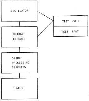
Figure 4 2 Block Diagram Of Eddy Current Inspection System
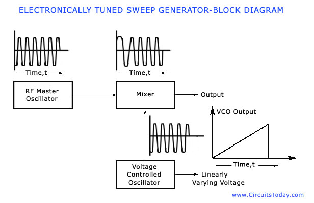
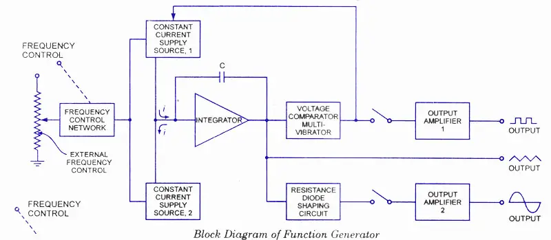
Sweep Frequency Generator Working Block Diagram Parameters
Magnetic Tape Recorder Working Principle Basic Components
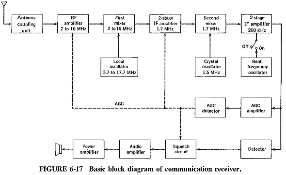
Communication Receiver Block Diagram Extensions Of

Digital Motion Controllers