Block Diagram Qpsk
Quadrature Phase Shift Keying Tutorialspoint

Block Diagram Of Qpsk Modulator Download Scientific Diagram

Schematic Diagram Of A Quadrature Phase Shift Keying Qpsk

Schematic Diagram Of A Quadrature Phase Shift Keying Qpsk

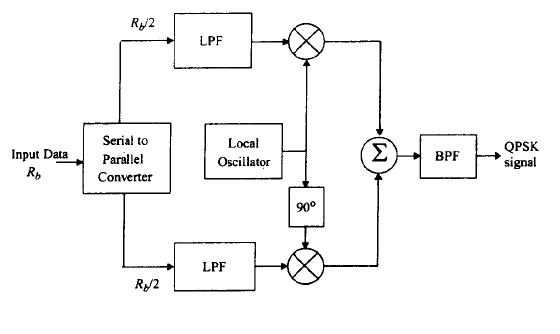
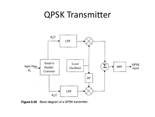
4 Block Diagram Of A Qpsk Transmitter 5 Shows A Block Diagram Of
Modulation

Block diagram of the spread spectrum qpsk modulator the sequence should be long enough with respect to the message signal to have the noise like spectrum.
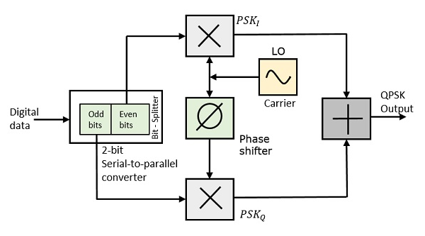
Block diagram qpsk. At the modulator s input the message signal s even bits i e 2 nd bit 4 th bit 6 th bit etc and odd bits i e 1st bit 3 rd bit 5 th bit etc are separated by the bits splitter and are multiplied with the same carrier to generate odd bpsk called as psk i and even bpsk called as psk q. Each frame contains 20 hello world messages and a header. Notice that the pn sequence is introduced here to both in phase i and quadrature q components. This is called pi 4 qpsk the constellation diagram of qpsk will show the constellation points lying on both x and y axes this means that the qpsk.
The block diagram is pretty simple to understand. S i t 2e s t cos 2πf c t 2n 1 π4 n 1 2 3 4 when n 1 the phase shift is 45 degrees. The following equation outlines qpsk modulation technique. A block diagram of such a system is shown in figure 2 below.
In binary phase shift keying bpsk the phase of a stable amplitude carrier signal is toggled amid two values with respect. In qpsk the same modulator is used but with binary messages in both the i and q. This video lecture discusses the block diagram of qpsk generation. Quadrature phase shift keying qpsk qpsk is a form of phase modulation technique in which two information bits combined as one symbol are modulated at once selecting one of the four possible carrier phase shift states.
The qam modulator is so named because in analog applications the messages do in fact vary the amplitude of each of the dsbsc signals. Binary phase shift keying bpsk is a form of phase modulation using two different carrier phases to signal 1 and 0. The bit generation subsystem uses a matlab workspace variable as the payload of a frame as shown in the figure below. The qpsk generation and detection has been expained here.
Hope it helps thanks. Basics of quadrature phase shift keying qpsk are covered in this. The transmitter includes the bit generation subsystem the qpsk modulator block and the raised cosine transmit filter block. The block diagram of the dsss communication system for qpsk is presented in figure 6.
The first 26 bits are header bits a 13 bit barker code that has been. The complete waveform simulation for the. Multipliers adder s are used. Pulse shaped before reaching the modulator.
In both the images qpsk transmitter is shown and it s constellation diagram is given. The timing diagram for bpsk and qpsk modulation is shown in figure 2.
Ec 2401 Wireless Communication Unit 3

Block Diagram Of Coherent Optical Qpsk Transmitter Download
Http Www Idc Online Com Technical References Pdfs Electronic Engineering Qpsk Modulation And Demodulation Pdf

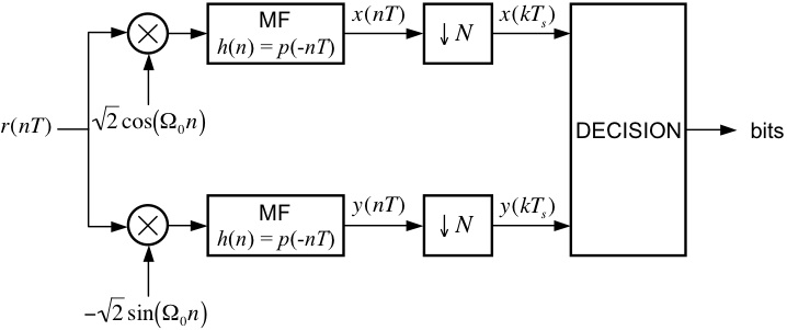
11 Qpsk Demodulator Block Diagram Download Scientific Diagram

Block Diagram Of Basic Qpsk Qam Digital Receiver Download
Quadrature Phase Shift Keying
Block Diagram Of Qpsk And 8 Psk Modulators Download Scientific

Fpga Implementation Of Low Power Digital Qpsk Modulator Using

Receiver Block Diagram Of An Sfh Qpsk System Download

Ppt Ee 6331 Spring 2009 Advanced Telecommunication Powerpoint

Pdf Short Range Ultrasonic Communications In Air Using Quadrature
Generalized Functional Diagram Of A Typical Qpsk Modem A

Qpsk Transmitter And Receiver Matlab Simulink Mathworks
