Block Diagram Reduction Feedforward
Http Www Cs Mun Ca Av Old Teaching Cs Notes Reduc Printout Pdf
Https Uotechnology Edu Iq Dep Mechanicsandequipment Lectures 20and 20syllabus Lectures Same Fourth 20grade Control 20and 20instrumentation Pdf Pdf
Control Systems Block Diagram Reduction Tutorialspoint
Http Deltauniv Edu Eg New Engineering Wp Content Uploads Lecture 5 Block Diagram Representation Of Control Systems Pdf
Https Www Benardmakaa Com Wp Content Uploads 2018 05 Block Diagrams Reduction Pdf
Problem 1 On Block Diagram Reduction Youtube

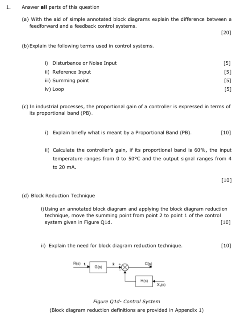
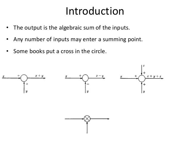
By means of systematic block diagram reduction every multiple loop linear feedback system may be reduced to canonical form.
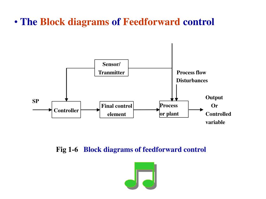
Block diagram reduction feedforward. Block diagram reduction feedforward loop. In this unit we will consider how to combine the blocks corresponding to individual subsystems so that we can represent a whole system as a single block and therefore a single transfer function. Block diagrams feedback and transient response specifications this module introduces the concepts of system block diagrams feedback control and transient response specifications which are essential concepts for control design and analysis. Figure 9 1a gives the traditional block diagram of a feedforward control system seborg et al 1989.
By means of systematic block diagram reduction every multiple loop linear feedback system may be reduced to canonical form. The block diagram of a practical feedback control system is often quite complicated. Feb 2 2011 1 i have come across a block diagram that has me stumped. Note that if the version of matlab you are using does not support the parallel function you will need to manually calculate the parallel connection of g1 and g2 in the above diagram.
Start date feb 2 2011. Joined may 2 2009 8. Figure 9 1b shows the same block diagram but redrawn so as to show clearly that the feedforward part of the control system does not affect the stability of the feedback system and that each system can be designed independently. Rule 2 check for the blocks connected in parallel and simplify.
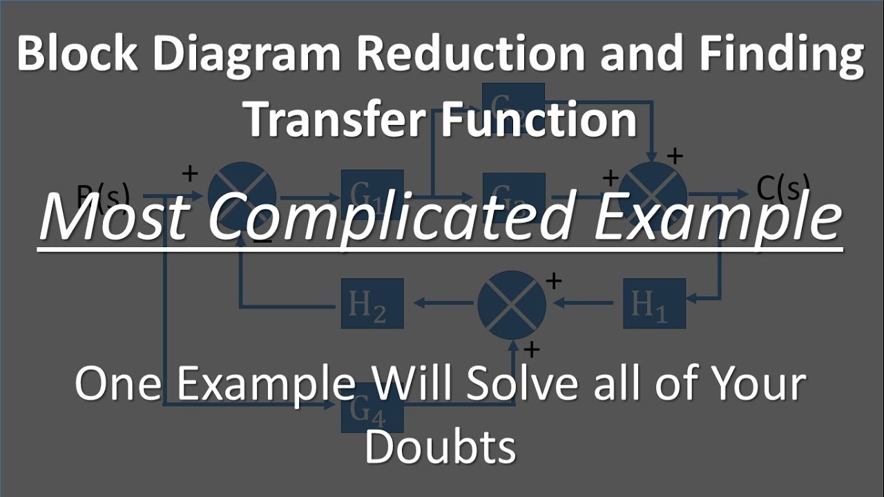
It may include several feedback or feedforward loops and multiple inputs. Two critical laws explanation please watch video along with this description to get better understanding rule. It may include several feedback or feedforward loops and multiple inputs. Learn all the block diagram reduction rules just by watching this one simple video.
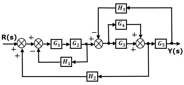
Eliminating the minor feedforward path we obtain figure 3 45 b which can be simplified to that shown in figure 3 5 c the transfer function c s r s is thus given by. This command loads the functions required for computing laplace and inverse laplace transforms. Here is an example of this. Obviously if it had a block it would.
Block diagram reduction write an m file to find the overall transfer function of the following system where and. Rule 1 check for the blocks connected in series and simplify. Block diagram reduction subsystems are represented in block diagrams as blocks each representing a transfer function. What has me stumped is the loop with no block on it.
Thread starter electromech man. The block diagram of figure 3 44 can be modified to that shown in figure 3 45 a.

Block Diagram Algebra Its Use In Feedforward Compensation Ppt
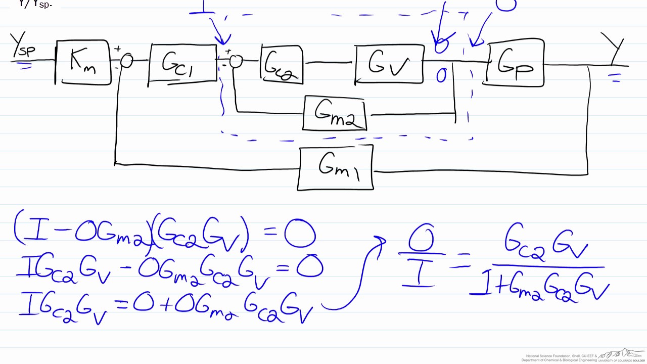
Transfer Functions For Cascade Control Using A Block Diagram Youtube
Http Web Engr Oregonstate Edu Webbky Mae4421 Files Section 202 20block 20diagrams 20 20signal 20flow 20graphs Pdf
Wescott Design Services Using Block Diagrams

Closed Tank Dp Level Transmitter With Wet Leg Zero Elevation
Block Diagram

Block Diagram Representation Of A Pi Controller With Saturation

Pid Controller Loop Tuning Questions And Answers Part 1 Pid
Solved 1 Find The Feedforward Open Loop And Closed Loo

Repaired Slicer For Client In Brunei Outdoor Decor Decor Home

Block Diagram Of Typical Power Management System Download
Block Diagram Reduction Control System Examples Youtube
Ppt The Introduction Of Automatic Process Control Powerpoint