Micrologix 1100 Wiring Diagram

Rslogix 500 Training Wiring Your Allen Bradley Micrologix 1100 Plc
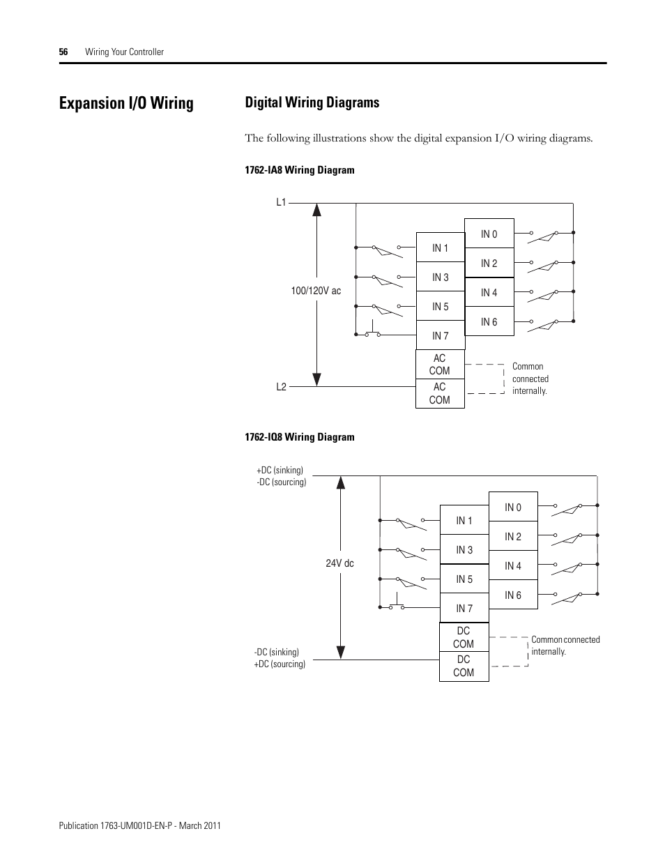
Expansion I O Wiring Digital Wiring Diagrams Rockwell

Gm 8370 Wiring Diagram Home Work Wiring Diagram Micrologix 1400

Sinking And Sourcing Wiring Diagrams Rockwell Automation 1763

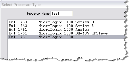
Rockwell Automation 1763 Micrologix 1100 Programmable Controllers

Rockwell Automation 1763 Micrologix 1100 Programmable Controllers

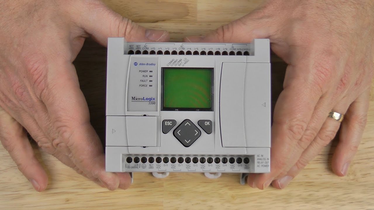
Micrologix 1100 wiring you should get a power line bottom left corner and network cable top left corner like the picture below.
Micrologix 1100 wiring diagram. Wiring your controller the following illustrations show the wiring diagrams for the micrologix 1100 wiring diagrams controllers. Our bulletin 1763 micrologix 1100 programmable logic controller systems add embedded ethernet ip on line editing and an lcd panel to the micrologix family. Controllers with dc inputs can be wired as either sinking or sourcing inputs. Because of the many.
Micrologix 1100 programmable logic controller systems. Depending on the specific model the micrologix 1100 is powered by 12 24v dc or 120 240v ac. Micrologix 1100 programmable controllers catalog numbers 1763 l16awa 1763 l16bwa 1763 l16bbb 1763 l16dwd topic page important user information 4 additional resources 5 overview 6 controller description 7 hazardous location considerations 8 mounting the controller 9 connecting 1762 i o expansion modules 15 wiring the controller 16. Plc hardware and the micrologix.
4 programming overview provides an overview of principles of machine control a section on file organization and addressing and a program development model. Refer to your rslogix 500 programming software user documentation for more information on programming your micrologix 1100 controller. Micrologix 1400 wiring diagram thanks for visiting my website this message will review regarding micrologix 1400 wiring diagram. Specifically this equipment is intended for use in clean.
Hardware 2 wiring your controller provides wiring guidelines and diagrams. Sinking and sourcing does not apply to ac inputs refer to sinking and sourcing wiring diagrams on page 3 50. All wiring must comply with n e c. 8 micrologix 1400 programmable controllers publication 1766 in001e en p april 2017 overview micrologix 1400 controllers are suitable for use in an industrial environment when installed in accordance with these instructions.
The built in lcd panel shows controller status i o status and simple operator messages. Do not connect a micrologix 1100 controller to another micrologix family controller such as micrologix 1000 micrologix 1200 or micrologix 1500 using a 1761 cbl am00. Refer to publication 1763 rm001 micrologix 1100 programmable controllers instruction set reference manual for the micrologix 1100 instruction set and for application examples to show the instruction set in use.
Micrologix 1100 Terminals Youtube
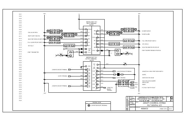
Montpelier Steam Plant 1056e 1 Thru 5

Allen Bradley Micrologix Plc Instructions

Rslogix 500 Analog Circuits Wiring And Programming 0 10vdc 4

1e6 8 Pin Ethernet Wiring Diagram Wiring Library

Allen Bradley Micrologix Trainer Basic Wiring To Get Started
Https Cdn Automationdirect Com Static Manuals Ea1mguserm Ch6 Pdf

Trn Icp Ml1100 Aio Allen Bradley Micrologix 1100 Plc Trainer With

Allen Bradley Micrologix 1200 Connection Guide

Micrologix 1762 If4 Analog Input Module Pdf Free Download
Rslogix 5000 Tips And Tricks
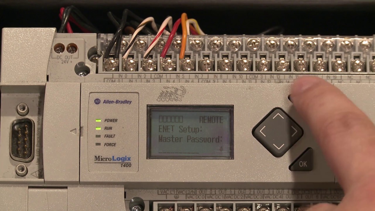
Setting The Ip Address On A Micrologix 1400 Youtube
