Miller Cycle Engine Diagram

Miller Cycle An Overview Sciencedirect Topics

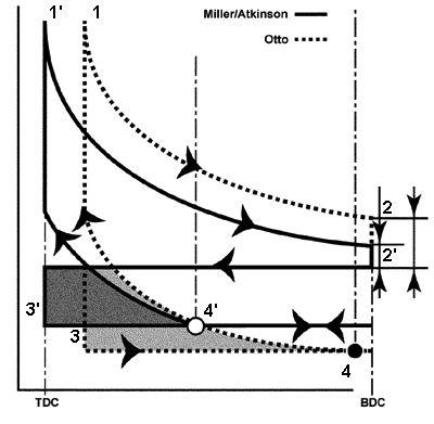
A Comparison Between Otto Cycle And Miller Cycle Diagram 30

P V Diagram Of A Miller Cycle Download Scientific Diagram
Mazda Cx 5 Service Repair Manual Miller Cycle Engine General

Miller Cycle Prof Timothy Marbach Me258 Advanced Thermodynamics
Atkinson Or Miller

A four cylinder 3 50 liter automobile engine operates on an ideal miller cycle with early closing intake valves shown in figure 13 52b.
Miller cycle engine diagram. Miller cycle can improve gasoline engine efficiency and fuel economy and is currently being used on many engines today. A miller cycle engine leaves the intake valve open during part of the compression stroke so that the engine is compressing against the pressure of the supercharger rather than the pressure of the cylinder walls. In engineering the miller cycle is a thermodynamic cycle used in a type of internal combustion engine the miller cycle was patented by ralph miller an american engineer us patent 2817322 dated dec 24 1957. New technologies allow higher amounts of miller pushing the benefits further without sacrificing engine performance.
Miller cycle engine umotor jorge pinto. 1 where and are the temperatures of the working fluid in state points 1 2 3 4 and 5. Motorgiga tv 152 383 views. This image miller cycle sequential valve timing s vt continuously with valve timing diagram for petrol engine previously mentioned is usually classed together with.
It has a compression ratio of 8 00 to 1 and an expansion ratio of 10 0 to 1. A miller cycle engine depends on a supercharger. Compression ratio 8 4 3500 rpm intake pressure 0 4 bar net imep 2 9 bar optimal spark timing is a function of operating condition peak pressure at 14 17o atdc for mbt ideal models of engine processes table 5 1. The engine may be two or four stroke and may be run on diesel fuel gases or dual fuel.
Ciclo otto vs ciclo atkinson vs ciclo miller duration. Unsubscribe from jorge pinto. The turbocharger provides air at 200. This type of engine was first used in ships and stationary power generating plants and is now.
Engine cycles in which the effective compression ratio is smaller than the effective expansion ratio are referred to as over expanded cycles the miller cycle is an over expanded cycle implemented with either early eivc or late livc intake valve closing. Miller cycle has been implemented in both diesel and spark ignited engines. The effect is increased efficiency at a level of about 15 percent. 5 1 pressure volume diagram of firing si engine.
Actual valve timing diagram for four stroke petrol engine valve timing diagram for 2 stroke petrol engine valve timing diagram for a four stroke cycle petrol engine. Vnt turbos a key enabler for higher levels of miller have been. The heat addition occurs in the constant volume process.

Hr12ddr Engine Nissan Technological Development Activities

Thermodynamic Modeling Of Performance Of A Miller Cycle With

Volkswagen S 1 5l Miller Cycle Engine How Does It Work Vwvortex

Miller Cycle With Eivc Download Scientific Diagram
Https Encrypted Tbn0 Gstatic Com Images Q Tbn 3aand9gcqc1y6eeane5ljachi Z429bsgtxch182ggjlebdavfgv6o0qoe Usqp Cau

Pdf Performance Study For Miller Cycle Natural Gas Engine Based

P V Diagram For The Air Standard Miller Cycle Download

Cat The Electronic Age Of Engines The Best Of All Worlds
What Is The Difference Between A Miller Cycle Engine And An
Http Papers Sae Org Gsdownload Prodcd 2015 24 2440

Three Types Of Atkinson Cycle 70 71 Download Scientific Diagram
.png)
Ab Engine Market To Watch Market Presentation On Youtube Please

An Analytic Study Of Applying Miller Cycle To Reduce Nox Emission
